
GitHub is home to over 40 million developers working together to host and review code, manage projects, and build software together. Sign up An 8-bit adder-subtractor made of full adders in Verilog. Testbench Code- 4bit Adder `timescale 1ns / 1ps ///// // Company: TMP // Create Date: 08:15:45 // Module Name: 4bit Adder // Project Name: 4bit Adder. Verilog program for Half Adder Verilog program for Full Adder Verilog program for 4bit Adder Verilog program for Half Substractor.
You know how to do addition using step-by-step. Always, the carry value is add to next step and the sum value is written to result. I tried to tell these in a picture:
If we want to write an algorithm for these, how to do this?
1. Variables Cx designer software download. | Inputs:a (4 bit), b (4 bit) Outputs:sum (4 bit), carry (1 bit) Others:carryValuesFromFullAdders (5 bit) (With this, we store carry values and use this value next step. Always, first bit is 0, because of there isn’t any operation before first bit pair so there is no ‘carry in’ value.) |
| 2. Full Adder for Every Bit Pair | Use full adder step-by-step for bit pairs, so when finish last step, we have final result. |
Verilog code for the algorithm:
1. Full Adder Code (We Need! You can use another codes like the previous blog post):

2. Four Bit Adder Code:
Bonus – Test Code:
Here, test result 🙂
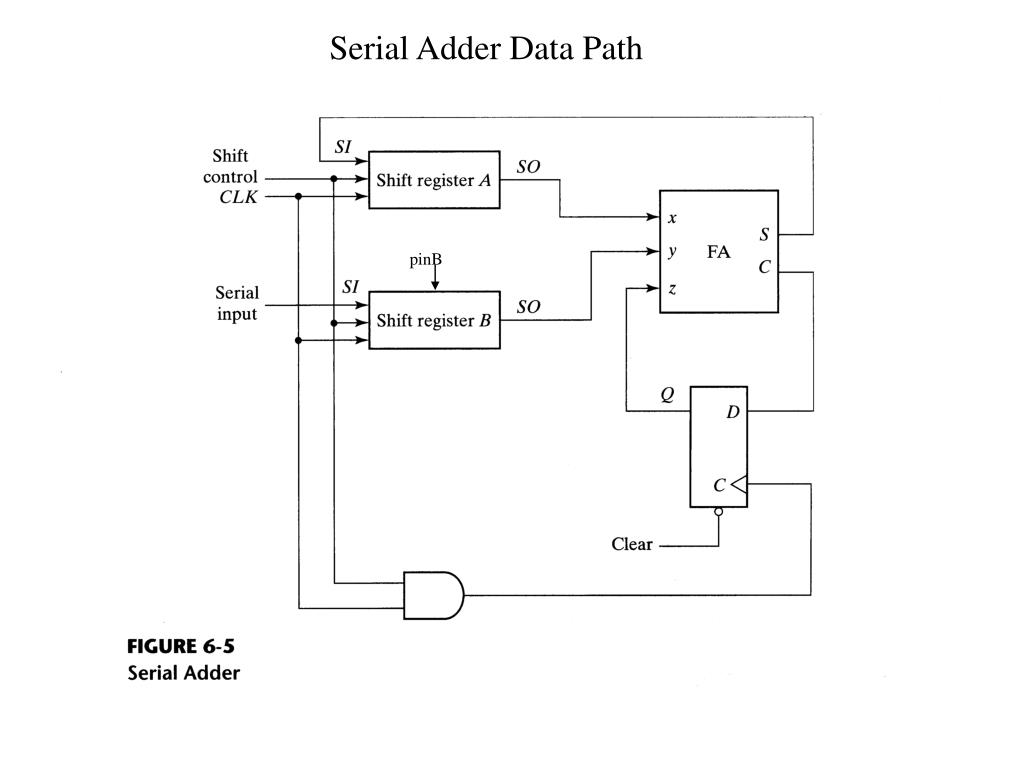
This repository contains behavioral code for Serial Adder.The following individual components have been modeled and have been providedwith their corresponding test benches:
- Parrallel Input Serial Output Shift register (PISO) (
piso.v) - D Flip Flop (
d_flipflop.v) - Full Adder (
full_adder.v)
File serial_adder.v is the master node, the corresponding testbench isserial_adder_tb.v. To compile and visualise the waveforms (using iverilogand gtkwave), follow these steps:
- Install
iverilogandgtkwaveusing the instructions given here. - Clone this repository using the command
git clone https://github.com/RJ722/serial-adder-verilog. cd serial-adder-verilogiverilog -o serial_adder.out serial_adder_tb.v./serial_adder.outgtkwave serial_adder_tb.vcd # Visualise waveforms
For changing the input values to the adder, please make changes in serial_adder_tb.v.
- Author: admin
- Category: Category
Search
Latest Articles
- Bypass Cpanel License Crack
- Beyblade Metal Masters Episode 3
- Download Drivers For Samsung Laptop Np300e5z
- Gta 5 Weapons Cheat Pc
- Vadivelu Punch Dialogues In Tamil Free Download
- 10 Edition Biology Mader 11
- Autocad 2000lt To Purchase
- Disordered Voice Database And Program
- Cod4 Pc Mod Menu With Bots Download
- Cesar Lcpc Keygen Music
- Manvasanai Serial Episode 1

GitHub is home to over 40 million developers working together to host and review code, manage projects, and build software together. Sign up An 8-bit adder-subtractor made of full adders in Verilog. Testbench Code- 4bit Adder `timescale 1ns / 1ps ///// // Company: TMP // Create Date: 08:15:45 // Module Name: 4bit Adder // Project Name: 4bit Adder. Verilog program for Half Adder Verilog program for Full Adder Verilog program for 4bit Adder Verilog program for Half Substractor.
You know how to do addition using step-by-step. Always, the carry value is add to next step and the sum value is written to result. I tried to tell these in a picture:
If we want to write an algorithm for these, how to do this?
1. Variables Cx designer software download. | Inputs:a (4 bit), b (4 bit) Outputs:sum (4 bit), carry (1 bit) Others:carryValuesFromFullAdders (5 bit) (With this, we store carry values and use this value next step. Always, first bit is 0, because of there isn’t any operation before first bit pair so there is no ‘carry in’ value.) |
| 2. Full Adder for Every Bit Pair | Use full adder step-by-step for bit pairs, so when finish last step, we have final result. |
Verilog code for the algorithm:
1. Full Adder Code (We Need! You can use another codes like the previous blog post):

2. Four Bit Adder Code:
Bonus – Test Code:
Here, test result 🙂
This repository contains behavioral code for Serial Adder.The following individual components have been modeled and have been providedwith their corresponding test benches:
- Parrallel Input Serial Output Shift register (PISO) (
piso.v) - D Flip Flop (
d_flipflop.v) - Full Adder (
full_adder.v)
File serial_adder.v is the master node, the corresponding testbench isserial_adder_tb.v. To compile and visualise the waveforms (using iverilogand gtkwave), follow these steps:
- Install
iverilogandgtkwaveusing the instructions given here. - Clone this repository using the command
git clone https://github.com/RJ722/serial-adder-verilog. cd serial-adder-verilogiverilog -o serial_adder.out serial_adder_tb.v./serial_adder.outgtkwave serial_adder_tb.vcd # Visualise waveforms
For changing the input values to the adder, please make changes in serial_adder_tb.v.
Search
Latest Articles
- Bypass Cpanel License Crack
- Beyblade Metal Masters Episode 3
- Download Drivers For Samsung Laptop Np300e5z
- Gta 5 Weapons Cheat Pc
- Vadivelu Punch Dialogues In Tamil Free Download
- 10 Edition Biology Mader 11
- Autocad 2000lt To Purchase
- Disordered Voice Database And Program
- Cod4 Pc Mod Menu With Bots Download
- Cesar Lcpc Keygen Music
- Manvasanai Serial Episode 1